GRACE TECHNICAL REPORTS
A Model-Driven Framework for Constructing
Runtime Architecture Infrastructures
H. Song
Y. Xiong
Z. Hu
G. Huang
H. Mei
GRACE-TR-2008–05
Dec. 2008
CENTER FOR GLOBAL RESEARCH IN
テクニカル・レポートは、国内外の論文誌、
Proceedings
等への投稿原稿、マニュアル、資料、研究の中間報告です。著作権は、全て著者に属します。ただし、同一ある
いは類似の論文が外部の論文誌等で発行される場合はホームページへの掲載等を中止
A Model-Driven Framework for Constructing
Runtime Architecture Infrastructures
Hui Song
∗†Yingfei Xiong
‡Zhenjiang Hu
†‡Gang Huang
∗Hong Mei
∗∗
Key Laboratory of High Confidence Software Technologies
Ministry of Education, Peking University, Beijing, China
{
songhui06,huanggang,meih
}
@sei.pku.edu.cn
†GRACE Center, National Institute of Informatics,
Tokyo, Japan,
[email protected]
‡
Department of Mathematical Informatics
University of Tokyo, Tokyo, Japan
[email protected]
December 2008
Abstract
Maintaining software systems at runtime becomes more and more im-portant, and many researchers are considering the use of architectural models for runtime management. For the research and application of architecture-based runtime management, one unavoidable issue is how to maintain the causal connection between the architectural model and the system state, which are heterogeneous in structures. To address this is-sue, researchers have proposed and implement many runtime architecture infrastructures to maintain causal connection between the specific archi-tecture and system concerned in their approaches, but as there are so many kinds of architectural models and systems, a framework is neces-sary to assist subsequent researchers or developers in constructing such infrastructures between them. In this paper, we report a model-driven framework, along with supporting tools we implemented, for constructing runtime architecture infrastructures. With the help of code generation and bidirectional model transformation, we support developers to con-struct infracon-structures by just writing two MOF meta-models and a QVT transformation between them. We evaluate the usage and effectiveness of our framework through a case study for achieving the runtime manage-ment of JOnAS systems based on C2-styled architectural models.
1
Introduction
runtime management [5], and many of the mainstream platforms provide some form of management capabilities to enable external management agents (either human administrator or software-based agents) to monitor and control it at runtime [14, 21]. On the other hand, on the research of different forms of man-agement activities, such as human-directed runtime evolution [18] or automatic self-adaptation [11], many researchers are considering abstracting the system states into some kind of models [10], especially architectural models. Archi-tectural models shield out the complex and technical details, and provide an abstract and usually domain-specific view of the running system states. Man-agement agents can monitor and control the systems by reading and writing their architectural model in proper forms.
There are many research approaches towards architecture-based runtime management, focusing on different issues, from low-level mechanism [5, 24, 13] to high-level management assistance [6, 11, 18], but one issues is unavoidable for all these approaches, i.e. how to make sure the architectural model reflects the current system states and in the mean time the system states will be changed correctly according the architectural changes [10, 3]. Some researcher name this issue as “maintaining the causal connection between architectural model and system states” [5, 13, 3], and name the particular parts in their approaches for maintain causal connections as “runtime architecture infrastructures”[18]. We follow these two name in the rest of this paper to simplify the discussion. Although it is not the main concern for all the approaches mentioned above, re-searchers of all these approaches did propose different but effective methods for maintaining causal connections, and implement corresponding infrastructures, usually specific to the kinds of architecture models and running systems they chose.
Only individual infrastructures are not enough. There are many different kinds of running systems with different management capabilities, and there are also many architecture styles, fitting for different domains and management capabilities. If a developer wants to provide a proper kind of architectural models for managing a specific kind of running system, she usually has to first put much effort on implementing an infrastructure to connect the architecture and the system, even if this is not her main concern. And moreover, these particularly constructed infrastructures are often inevitable to have some kinds of little defects, and are often not easy for maintenance. It is also a hard task for developers to demonstrate the correctness of their infrastructures to the users or subsequent developers. Having noticed this problem, some researchers begin to consider a framework to help constructing such infrastructures.
Existing frameworks, as far as we know, still have some limitations. The authors of Rainbow [11] summarized a common structure of architecture-based self-adaptable systems, and identified the reusable parts, but they did not pro-vide automatic supports for constructing all these parts; In their succeeding work [20], they provide a high-level language for specifying the relation between system and architecture, along with an engine to execute this language, but their language and engine are unidirectional, which cannot propagate the archi-tecture change into running system; Genie [4] supports a model-based approach for developing self-adaptive systems, but currently this tool is specific to one kind of running systems, i.e. the systems running upon the Gridkit reflective middleware platform.
constructing runtime architecture infrastructures in a model-driven approach. By utilizing bidirectional transformation [9, 22] and model difference [1] in a well-designed process, we support the maintaining of causal connections in both directions. And moreover, by utilizing the standard model-driven techniques of MOF, QVT and code generation, our framework can be used between different kinds of architectures and systems, in a unified, model-driven way.
The advantages of our framework can be summarized as follows.
• Our framework can improve the productivity. Developers can construct an infrastructure by specifying two MOF meta-models, writing a QVT transformation and supplementing a small quantity of code. The mecha-nism for maintaining the causal connection is transparent to developers. We will demonstrate the improvement on productivity in our cased study.
• The behavior of the obtained infrastructures is clear, predictable, and stable. For a constructed infrastructure, the architecture style, the sys-tem management capability and consistency relation between them are all specified explicitly, under formal and standardized languages, and we also prove that the constructed infrastructures preserve some key proper-ties. In addition, the clear behavior also makes our framework good for maintenance and incremental development.
• We separate the development into three relatively independent concerns. When a developer is in charge of specifying the system states, he or she does not need to care about the architecture and the relation. This makes the specification of one kind of systems, along with the filled hook methods, reusable for different architecture styles. It is also the case for specifying architectural model and the relation.
The rest of this paper is organized as follows. Section 2 gives an overview of runtime architecture infrastructures, and how our framework supports con-structing such infrastructures. Section 3 and Section 4 introduce how we support specifying and accessing architectural models and system states in a unified, model-driven way. Section 5 discusses how to specify the relation between ar-chitecture and system using QVT relational, and how we achieve maintaining causal connections according to such QVT specification. Section 6 presents a case study for supporting managing JOnAS [16] systems based on C2 styled architecture [18].
2
Runtime Architecture Infrastructures
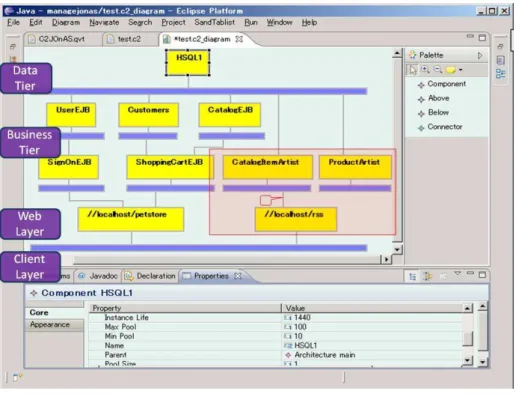
Figure 1: A snapshot of using C2 architecture to manage JPS on JOnAS
2.1
An example of architecture-based runtime
manage-ment
We consider a typical example of architecture-based runtime management, i.e. using a C2-styled architecture model to manage Java Pet Store (JPS) [15] run-ning on JOnAS application server [16]. JPS is a J2EE blueprint application implementing an online retail website, and JOnAS is a widely used open source J2EE application server. JOnAS provides powerful management capability un-der JMX standard [14] for monitoring and configuring systems states, and de-ploying or undede-ploying components (EJB, Database, Services, etc), at runtime. By default, maintainers can manage the applications on JOnAS (like JPS) by writing Java code to directly access the management API, or manipulate a build-in web-based user interface. These two ways are powerful enough, but not the best ways for every situation. If a maintainer is familiar with online shop (in problem space), but not familiar with J2EE standards (in solution spaces), these two ways are difficult for him to grasp. Architecture-based management is a better choice in such situations. Researchers are working for years on an architecture style named “C2” [18], which is proper for design and runtime management of GUI oriented systems like JPS.
four layers of web-based applications as marked in the snapshot, and it is also a hierarchical model (the “Customers” component encapsulate some components dealing customer information). These features make it easy for maintainers to understand and manipulate.
To use this architectural model for runtime management, we first develop a runtime architecture infrastructure. Now maintainers can launch a “syn-chronize” command to ask this infrastructure to synchronize the architectural model and the system state. After the first synchronization, some components will reflect the current state or configuration information of their corresponding implementation elements (EJB, Database...). For example, through the bottom part of Figure 1, maintainers can see that the current busy connection to this data source is 1, and the size of connection pool is configured between 10 and 100. Maintainers can change some value on this window, e.g. reduce the max pool size to 50, and after launching “synchronization”, the max pool size of the database will be changed at runtime. The maintainers can also use this archi-tectural model for runtime evolution. For example, suppose they would like to supplement an RSS function to the JPS system, he can add new components, like the ones in the red frame in Figure 1, just in the same way as supplement a design model. Then they can provide this new architectural model to some J2EE experts for developing corresponding EJBs or Web Modules. Finally, they can add some necessary information to these components, like names and file paths pointing to development result, and launch “synchronization” again. Now the implementation EJBs and Web Modules are automatically deployed into the running system, and users can use the url “http://localhost/rss” to retrieve an RSS seed with all pet item information. If the maintainer think the current RSS contents not satisfying, they can redirect the link from “//localhost/rss” component to the connector under “ProductArtist” component, and after syn-chronization, requesting the “http://localhost/rss” url will obtain an RSS seed with different contents.
During the whole management process, maintainers do not have to care about the J2EE specific techniques and concerns, as well as many irrelevant de-tails like the many middleware services and components for other applications. This example is just a simple illustration, and detailed discussion about the advantage of using C2 styled architecture for runtime evolution can be found in literature [18]. And moreover, using C2 styled architecture model for manual evolution is just one kind of architecture-based runtime management. We can also provide architectural models in other styles as different views for main-tainers with different concerns, and by employing the technologies presented in literature [6], we can also help achieve automatic management. The precon-dition is that we have effective runtime architecture infrastructures to connect these architectural models with the running systems.
2.2
Requirements for runtime architecture infrastructures
From the above example, we can go on to discuss the requirements for runtime architecture infrastructures. We first derive the the main capabilities a runtime architecture infrastructure should have, then we present some facts which have will affect the implementation of infrastructures, and finally we will discuss the meaning the causal connection by listing a set of properties.
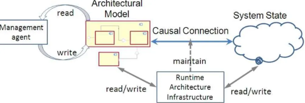
manage-Figure 2: A common structure of architecture-based runtime management
ment approaches. Management agents perform the system only by reading and writing the architectural model, through some kind of interfaces or modeling tools. To ensure these management activities effective on the real system, there needs to be a causal connection between the architecture and the system, and the infrastructure is in charge of maintaining this causal connection. In partic-ular, the infrastructure will read the architectural model and the system state, calculate the modifications needed on both of them to maintain the causal con-nection, and finally modify the architectural model and system states according to its calculation result. This is a common structure, and literatures [] also discussed about similar structures. From such a structure, we can summarize the three main capabilities of runtime architecture infrastructures, i.e. manip-ulating the architectural model, manipmanip-ulating the system state, and calcmanip-ulating how to maintain the causal connection.
Besides the structure and capabilities, we would also like to clarify some facts of architecture-based runtime management, and these facts have significant influence on the implementation of runtime architecture infrastructures.
• Fact 1. The structures of architecture model and the system state are not isomorphic. In the above example, the architectural model are hierarchi-cal, but in the running system, all EJBs locate in the same layer. Another example is that elements with the same type of “Component” may reflect different kinds of elements in the system. The essential of this heterogene-ity is that the architectural model and system states respectively locates in problem space and solution space
• Fact 2. Both architectural model and system state may contain informa-tion which are irrelevant to the other side. On the one hand, as archi-tectural model is usually an abstract view to the system state, there is certainly some information in system states which is not reflected. On the other hand, the architecture model may contain some information for easy to understand, like the comments on components or the layout in-formation between components, and such inin-formation will not relevant to system state.
after synchronization will not the be the same number as the maintainer have given. This uncertainty origins from the fact that the architectural model abstracts out many complex relations exists in the running system.
In the end of this sub section, we emphasize on the most important part of the requirements, i.e. the properties of maintaining causal connections, or in other words, what is the proper behavior of runtime architecture infrastructures. Commonly, the task of maintaining causal connection is simply defined as to ensure that the architecture model is an ongoing representation of the running system, that means the architecture should change as system changes, and vice versa. To discuss this task more strictly, we introduce a consistency relation between architectural model and system state, and if the current architectural model and the system state satisfy this relation (or in other word, if they are “consistent”), we say that this architectural model reflects the current system state.
• Property 1. Synchronization leading consistency. First of all, when man-agement agents launch the synchronization command, they definitely ex-pect that the resulted architectural model and system state are consistent, otherwise, they cannot get the correct system state or the system state does change as they want.
• Property 2. Non-interference reading. In order to check the fresh state of system by reading architectural models, management agents have to launch synchronization before reading. In such situations, the manage-ment agents make no change on the architectural model,and the infras-tructure should not do anything to interfere the running system and make its state change.
• Property 3. Effective writing If management agents make some changes on the architectural model and then launch synchronization, he wish that these changes remain in the resulted architectural model. That means the system has been changed properly according to these architectural changes. Note that according to Fact 3, sometimes this property may conflict to Property 1, and in such situations, the infrastructure should make the agents aware of that.
• Property 4. No insignificant change Sometimes, before synchronization the architecture and the system are already consistent. That may be because there are no changes on architecture and system, or the changes are all within the scope of irrelevant information (see Fact 2). In such situations, the infrastructure should not change any of them.
2.3
Constructing a runtime architecture infrastructure
In short, constructing a runtime architecture infrastructure is the work of im-plementing the 3 tasks.
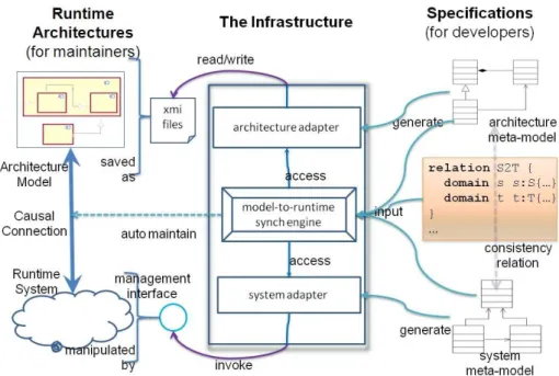
Figure 3: Approach overview
provided by the system, following some specific accessing method. The problem here is that the code for implementing these two tasks should be independent from the code for maintaining causal connection, otherwise, considering all these things together may make the logic very complex, and the constructed infras-tructure will be hard to maintain and reuse. Therefore, developers have to decide either to consider all things together, sacrificing the maintainability and reusability, or take some time to define clear and reusable interfaces between the three tasks. The latter choice itself is a non-trivial technical issue.
The third task is more difficult. First, according to Fact 1, calculating how to maintain causal connections is more complex than “comparing two piece of data, since the heterogeneity between architecture and system must be considered. Moreover, developers also have to consider the extra information (according to Fact 2), and try to deal with situations when the management activity failed (according to Fact 3). Finally and most importantly, to provide a effective causal connection infrastructure for management agents, developers also have to satisfy the four properties, and prove this satisfaction to the human maintainer who will use this infrastructure, or the subsequent developers who will develop the management agents based on this infrastructure.
From the above discussion, we can see that developing an effective runtime architecture infrastructure manually is complex and tedious. Nowadays, model-driven engineering has been wide-accepted as an approach to liberate develop-ers from such tedious manual work. In this paper, we report a model-driven approach for constructing runtime architecture infrastructures, along with a framework to support such an approach.
the infrastructure for maintaining causal connection between them. Here we make two assumptions. First, the architectural models are saved as XMI files. XMI is an OMG standard format for restoring models, so this assumption is reasonable. Second, the running system has provided a management interface for external software to manipulate its runtime state, this is also a common case for modern systems. Having these two assumptions, we can specialize the three tasks to “reading and writing XMI files”, “invoking management interface for retrieving and updating system state” and “calculating how to main the causal connection”. We divide the generated infrastructure into three independent parts for these three tasks, as shown in the middle part of Figure 3. The “Model-to-runtime synchronization engine” automatically interacts with the other two parts through an accordant interface which comply with the MOF reflection standard.
Our framework supports developers to construct these three parts in a model-driven way.
First, developers can define the meta-model of the architecture models using a standard meta-modeling language named MOF. This meta-model specifies what kinds of elements will appear in the architectural model, the attributes of these elements, and the possible association between them, and it is actually the specification of architecture style. From this meta-model, our framework will automatically generate Java code for reading and writing XMI files storing the architectural model.
Second, developers can use MOF to define the meta-model for system states, specifying the kinds of manageable elements, the attributes of these elements and the association between these elements, and use a fixed format of annota-tions to specify the system-specific ways for accessing these system states. From this meta-model, our framework will generate the system adapter for accessing the system’s management interface.
Finally, developers can use a model transformation language, QVT, to spec-ify the consistency rule he required between the architectural model and sys-tem state, and input the two meta-models and the consistency rule into a pre-implemented common synchronization engine. This engine can automatically retrieve the architectural model and the system state through the two adapters, calculating how to maintain the causal connection according to the consistency rules, and finally write the calculated changes back to the architecture and the system.
Notice that the steps in this constructing process are on the model level, and thus this approach has the common advantages of model-driven engineering, like productive, stable and maintainable. And moreover, we can also prove that the infrastructures constructed under our framework will satisfy the 4 properties of causal connection. This will not only deliberate developers from caring about the correctness of their infrastructures, but also deliberate them from convincing the users of their infrastructures.
3
Manipulating Architectural Models
synchro-nization engine can automatically manipulate the architecture models stored as XMI files, according to the defined architecture style.
It is natural to define an architecture style as a MOF meta-model. An architecture style defines what kinds of elements may exists in an architectural model (usually, but not necessarily, some kinds of components and connectors), the properties of each kind of elements, and the probable relationship between model elements. Users can use MOF classes, attributes and associations to define the the element types, properties and relationships, respectively. An example can be found in Figure 6, where we use a MOF meta-model to define an architecture style imitating C2.
Currently, we do not restrict the ways for defining “constraints” in an archi-tecture style, and users can choose some mature model-driven techniques like OCL. Note that to support architecture-based runtime management, researchers have tried to add dynamic features, like update operations, into architecture styles [19]. In our approach, developers do not need to specially define such dy-namic features, and we support the standard model modification like changing attribute, adding elements, etc. by default.
In our framework, we reuse a MOF implementation named Eclipse Modeling Framework (EMF) [7] to automatically construct an architecture adapter from the meta-model ∗. From the meta-model, EMF can generate a set of Java
classese, and these classes implement the standard MOF reflection interface. With the help of an XMI parser implemented by EMF, models stored as XMI files can be reified as a set of Java objects under those generated classes. The generated classes and the reused XMI parser forms an architecture adapter. The synchronization engine can automatically manipulate the models represented as Java objects through the standard interface, and the XMI parser ensure that these modifications have effects on the XMI files.
4
Manipulating System States
To construct system adapters under our framework, developers also just need to define the management states of the target systems using MOF meta-models. Constructing system adapters is more complex than constructing architecture adapters. Unlike architectural models that are all stored as a unified and stan-dard XMI files, system states hide behind various management interfaces, and each of these interfaces allows a specific method to access them. So the prob-lems are how to provide a simple way for developers to describe such system specific information, and how to automatically generate effect adapters for dif-ferent management interfaces from such descriptions. In this section, we first give an explanation about management states, and then discuss how to de-fine management states using MOF meta-models. During the defining process, we allow developers to add a series of annotations with system-specific access methods, and this is the solution to the first problem. Finally, we introduce our generation tool for addressing the second problem.
Management statesare system states which can be observed or manipulated
∗ Strictly speaking, EMF is not an implementation of MOF, because its meta-modeling
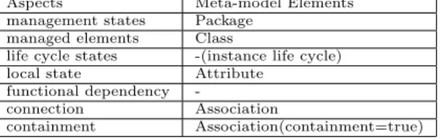
Table 1: Structural definition of management state
Aspects Meta-model Elements management states Package
managed elements Class
life cycle states -(instance life cycle) local state Attribute
functional dependency
-connection Association
containment Association(containment=true)
by management agents through some kind of management interface. Literature [21] gave a definition of management states by listing some common aspects. In the authors’ opinion, a system’s management state is composed of some
managed elements which can be retrieved through the management interface provided by the system. Each of the managed elements contains some local properties andlife cycle states, and may have some functional dependencies or
common connections with other managed elements, and a managed element may also contain other managed elements. Take a J2EE system as an exam-ple. The JMX implementation provided by the J2EE server is the management interface for manipulating the management state. From this JMX interface, we can manage different kinds of MBeans representing the EJBs, data sources or middleware services currently running in the server. These MBeans are the
managed elements. An MBean for a data source may contain somelocal proper-tieslike the maximal pool size of the database, and it may haveconnection with an EJB MBean because the EJB has to retrieve data from this data source.
To define the management states, developers must provide two kinds of information. “Structural definition” specifies the types of the aspects discussed above, using basic MOF meta-model elements. “Access method” specifies the system-specific way for manipulating these aspects. Developers provide this information by adding annotations into the defined meta-model elements. And in the annotations, they can write an extended version of Java code.
Table 1 summarizes a guidance for the structural definition. The first col-umn lists the aspects for management states according to literature [21]. The second column list the meta-model elements to use for defining the left aspects. Note that we do not require explicit definition for “life cycle states”, and such states can be reflected by the life cycle of model elements. We also ignored the “functional dependency”, because in architecture-based management, such constraint specifications should better be handled at architectural level.
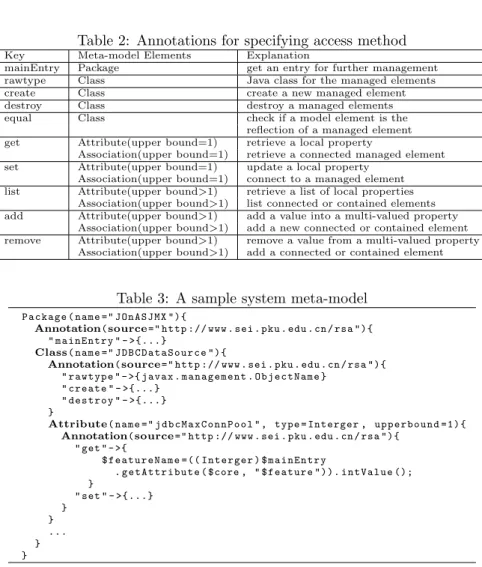
Table 2 lists the annotations a developer can add to specify the system-specific access method. For each kind of annotations, we list the annotation key name, the possible meta-model elements to annotate, and a short expla-nation about what information developers should provide through this kind of annotations.
Table 2: Annotations for specifying access method
Key Meta-model Elements Explanation
mainEntry Package get an entry for further management rawtype Class Java class for the managed elements create Class create a new managed element destroy Class destroy a managed elements equal Class check if a model element is the
reflection of a managed element get Attribute(upper bound=1) retrieve a local property
Association(upper bound=1) retrieve a connected managed element set Attribute(upper bound=1) update a local property
Association(upper bound=1) connect to a managed element list Attribute(upper bound>1) retrieve a list of local properties
Association(upper bound>1) list connected or contained elements add Attribute(upper bound>1) add a value into a multi-valued property
Association(upper bound>1) add a new connected or contained element remove Attribute(upper bound>1) remove a value from a multi-valued property
Association(upper bound>1) add a connected or contained element
Table 3: A sample system meta-model P a c k a g e ( name =" J O n A S J M X "){
Annotation(source=" http :// www . sei . pku . edu . cn / rsa "){ " m a i n E n t r y " - >{...}
Class( name =" J D B C D a t a S o u r c e "){
Annotation(source=" http :// www . sei . pku . edu . cn / rsa "){ " r a w t y p e " - >{ javax . m a n a g e m e n t . O b j e c t N a m e }
" create " - >{...} " d e s t r o y " - >{...} }
Attribute( name =" j d b c M a x C o n n P o o l " , type = Interger , u p p e r b o u n d =1) {
Annotation(source=" http :// www . sei . pku . edu . cn / rsa "){ " get " - >{
$ f e a t u r e N a m e =(( I n t e r g e r ) $ m a i n E n t r y
. g e t A t t r i b u t e ( $core , " $ f e a t u r e ")). i n t V a l u e (); }
" set " - >{...} }
} ... } }
the java code for creating a new data source runtime, and annotate the attribute with the Java code for retrieving the maximal size of this data source’s connec-tion pool. The text used inside an annotaconnec-tion is written by an extended version of Java. The identifiers starting with “$” are some variables used in generation time, and it will replace by a fix pattern of code during generation. Due to the restriction of paper length, we only present one annotation, and a detailed version of this meta-model can be found in Appendix 8.
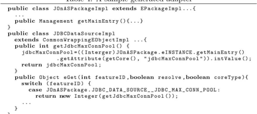
In our framework, we implement a code generation engine to automatically generate the system adapter from such meta-models, based on the EMF code generation. Inheriting from EMF, the generated Java classes from our engine also implements the MOF standard reflection interface. Besides these standard methods, this tool also generates a series of specific methods according to the annotations, and these specific methods can actually manipulate the system states. Finally, the framework contains some auxiliary classes which connect the standard methods with the specific methods. We use a sample to show how the generated system adapters work.
Table 4: A sample generated adapter
public c l a s s J O n A S P a c k a g e I m p l extends E P a c k a g e I m p l ...{ ...
public M a n a g e m e n t g e t M a i n E n t r y ( ) { . .. } }
public c l a s s J D B C D a t a S o u r c e I m p l
extends C o m m o n W r a p p i n g E O b j e c t I m p l ...{
public int g e t J d b c M a x C o n n P o o l () {
j d b c M a x C o n n P o o l =(( I n t e r g e r ) J O n A S P a c k a g e . e I N S T A N C E . g e t M a i n E n t r y () . g e t A t t r i b u t e ( g e t C o r e () , " j d b c M a x C o n n P o o l " )). i n t V a l u e ();
return j d b c M a x C o n n P o o l ; }
public Object eGet (int featureID ,boolean resolve ,boolean c o r e T y p e ){
switch ( f e a t u r e I D ) {
case J O n A S P a c k a g e . J D B C _ D A T A _ S O U R C E _ _ J D B C _ M A X _ C O N N _ P O O L :
return new I n t e g e r ( g e t J d b c M a x C o n n P o o l ()); ...
} }
getJdbcMaxConnPool andgetMainEntryare examples of thespecific methods, which are generated according to the “mainEntry” and “get” annotations, re-spectively. When the synchronization engine wants to know the max pool size of an data source, it will automatically invoke theeGetwith the proper featureID (it gets the meta information like class name and feature ID from the meta-model), andeGet will forward the invocation togetJdbcMaxConnPool, where the value will be retrieved from the J2EE server and returned. We choose a very simple example for the ease of comprehension, and other parts of the generated code are more complex. For example, if the synchronization engine wants to get all the data sources and calleGetautomatically, the generated adapter will finally return an object of a specially implemented List class, which is one of the auxiliary classes we implemented in the framework. This object will call the correspondinglistmethod generated from “list” annotation to get all the ObjectNames representing the available data sources in the current system, and instantiate a set of Java objects of the typeJDBCDataSourceImplto wrap these ObjectNames, so that the synchronization engine can go on to manipulate these data sources through their wrappers. The implementation of this generation tool is not the emphasis of this paper, and technical details will be discussed in a later literature.
5
Maintaining Causal Connections
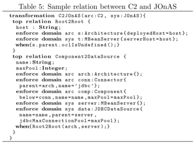
Table 5: Sample relation between C2 and JOnAS
transformation C 2 J O n A S ( arc : C2 , sys : JOnAS ){
top relation R o o t 2 R o o t {
host : String;
enforce domain arc s : A r c h i t e c t u r e { d e p l o y e d H o s t = host };
enforce domain sys t : M B e a n S e r v e r { s e r v e r H o s t = host };
when{ s . parent . o c l I s U n d e f i n e d ();}
}
top relation C o m p o n e n t 2 D a t a S o u r c e {
name :String;
m a x P o o l :Integer;
enforce domain arc arch : A r c h i t e c t u r e {};
enforce domain arc conn : C o n n e c t o r { parent = arch , name = ’ jdbc ’ };
enforce domain arc comp : C o m p o n e n t { below = conn , name = name , m a x P o o l = m a x P o ol };
enforce domain sys server : M B e a n S e r v e r {};
enforce domain sys data : J D B C D a t a S o u r c e { name = name , parent = server ,
j d b c M a x C o n n e c t i o n P o o l = m a x P o o l };
when{ R o o t 2 R o o t ( arch , server );}
} }
Implementing this common synchronization engine is not trivial. First, when a change occurred at architectural model, we have to calculate what this change means for the system state according to the specified relation, and so is the change on system state. Second, when architecture and system change at the meantime, we have to merge these changes and calculate the correct subsequent modifications on architecture and system. Third, for system state, chances are that some modifications do not have expected effects, and for such situations we have to give a reasonable result for architecture-based management. We designed an algorithm based on QVT bidirectional transformation and model difference to address the above issues.
When developing under some framework, developers usually expect that the behavior of their product are predicable. On the basis of the properties of QVT bidirectional transformation and model difference (discussed in literature [22] and [1], respectively), we can demonstrate that our algorithm preserve a series of properties. From these properties, along with the unambiguous semantics of QVT transformation, developers can be clear about the behavior of their infrastructures constructed under our framework.
At the last of this section, we will report how we implement this algorithm.
5.1
Specifying relation between architectures and systems
We choose QVT relational language for developers to specify the relation be-tween architecture and system. Unlike operational transformation languages like ATL and QVT operation, QVT relational is not for specifying how to cre-ate a new model from an original one, but specifying a relation between two sets of models complying with two meta-models respectively.
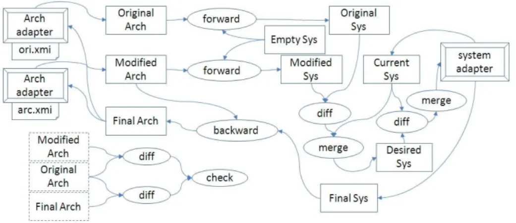
Figure 4: Synchronization algorithm
HereRoot2Rootcan be interpreted as follows: for each rootArchitecture (not an inner structure of some component) in the architectural model there must a MBeanServer in the system, and vice versa. And the Architecture’s deployedHost must equal to the MBeanServer’s deployedHost. The second relationComponent2DataSourcemeans that if there is aComponentlinked with a Connectorwith type “jdbc”, then there must beDataSourcewith the same name. Likewise, for eachDataSourcein the system, there must be a component with the same name, and linked with aConnectortyped “jdbc”.
We do not restrict the use of QVT language, that means any legal QVT relational transformation are acceptable by our framework.
5.2
Synchronization algorithm
An overview of our synchronization algorithm is shown in Figure 4. This algo-rithm processes two XMI files and a running system through the architecture adapter and system adapter. Before the execution of this algorithm, the two XMI files storing the architectural models before and after the management agent’s modifying, and after the execution, the system state is changed accord-ing the management agent’s modification, and the two XMI files reflect the current system state.
The basic idea of our algorithm is: get the system-side meaning of archi-tectural modifications by transforming the two archiarchi-tectural models into two system models respectively and calculate the difference between them, then try to manipulate the system according to the difference and retrieve the manipu-lation result, and finally transform the resulted system state back and reflect it in architectural level.
Before discussing the process, we first introduce the techniques we employed in this algorithm.
and then copy the constructed model. The arrows pointing to architec-ture adapter means manipulating system states, for which we will discuss later. Except for invoking adapters, the operations on the intermediate models (represented as common rectangles) do not affect XMI files or system states.
• Forward and backward transformationare bidirectional transforma-tions on the basis of the relation defined by QVT relational. Forward transformation “looks at a pair of models (m, n) and works out how to modify n so as to enforce the relation: it returns the modified version”. “Similarly, backward transformation propagate chages in the opposite di-rection” [22].
• Model difference[1] calculates the difference between two models under the same meta-model. The difference result is a set of model modifications like creation of a new element or update to a feature. Model merger
[1] is the operation for modifying a model according to a difference, and return the modified model. The arrow from a “diff” activity to the system adapter means merging the modifications in the difference result on the system state.
In the rest of this subsection, we use a small example to illustrate our al-gorithm step by step. This example is about about maintain causal connection between C2 architecture and JOnAS system. The meta-models, adapters and the relation required for this example has already been introduced as exam-ples in previous sections. We suppose that before synchronization, ori.xmi only restored an empty architecture, whilearc.xmicontains a Componentand a Connector, which are inserted by the management agent. At this time, the JOnAS server only contain a data source.
Step 1. Loading architectural models. According to the example descrip-tion, we get two models as follows. During the following discussion, we use a simple notation to express models. We express a model element beginning with its type at a non-indent line, and in the following lines, each with one indent, listing the features and their values. For example, the Modified Arc shown below contains tree model elements. The second element is a Component. Its name is"MySQL", its parent is the #127.0.0.1 and its maximal pool size should be 1000.
/∗Original Arc∗/
Architecture
d e p l o y e d H o s t = " 1 2 7 . 0 . 0 . 1 "
/∗Modified Arc∗/
Architecture
d e p l o y e d H o s t = " 1 2 7 . 0 . 0 . 1 " , c o m p o n e n t =# MySQL , c o n n e c t o r =# jdbc
Component
name = " MySQL " , parent =#127.0.0.1 ,
below =# jdbc , m a x P o o l =1000
Connector
name = " jdbc " , parent =0 , above =# MySQL
/∗Original Sys∗/
M B e a n S e r v e r
s e r v e r H o s t = " 1 2 7 . 0 . 0 . 1 "
/∗Modified Sys∗/
M B e a n S e r v e r
d e p l o y e d H o s t = " 1 2 7 . 0 . 0 . 1 " , j d b c D a t a S o u r c e =# MySQL J D B C D a t a S o u r c e
name = " MySQL " , parent =#127.0.0.1 , j d b c M a x C o n n e c t i o n P o o l =1000
Step 3. Retrieve System State. We invoke a model copy method from sys-tem adapter to a intermediate model namedCurrent Sys. During the copying process, this method will recursively invoke the standardgetmethods, so that the entire system state will be retrieved and stored in theCurrent Sysmodel. Currently, we assume that the JOnAS server only contain a data source named “HSQL”.
/∗Current Sys∗/
M B e a n S e r v e r
d e p l o y e d H o s t = " 1 2 7 . 0 . 0 . 1 " , j d b c D a t a S o u r c e =# HSQL J D B C D a t a S o u r c e
name = " HSQL " , parent =#127.0.0.1 , ...
Step 4. Merge the management agent’s modification. We first differ Modified Sys and Original Sys. The difference we obtained is actually the management agent’s intention on changing system state. We merge this dif-ference into Current Sys to get the Desired Sys, which is the system state expected by the management agent.
/∗Desired Sys∗/
M B e a n S e r v e r
d e p l o y e d H o s t = " 1 2 7 . 0 . 0 . 1 " , j d b c D a t a S o u r c e =# HSQL , j d b c D a t a S o u r c e =# MySQL J D B C D a t a S o u r c e
name = " HSQL " , parent =#127.0.0.1 , ...
J D B C D a t a S o u r c e
name = " MySQL " , parent =#127.0.0.1 , j d b c M a x C o n n e c t i o n P o o l =1000
Step 5. Try to reconfigure the system. DifferDesired Sys andCurrent Sys, and the resulted difference contains the modifications we need if we want to change the system state according to Desired Sys. The difference is showned below, in the format proposed by literature [1].
/∗Desired Sys − Current Sys∗/
[ [ new ( J D B C D a t a S o u r ce ,# MySQL ) ]
[ insert (#127.0.0.1 , j d b c D a t a S ou r c e , # MySQL ) , set (# MySQL , parent , # 1 2 7 . 0 . 0 . 1 )
set (# MySQL , j d b c M a x C o n n e c t i o n P o o l , 1000) ]
]
Table 6: Decision table for rechecking results
# Type Query i a Condition Explanation
1 new type, id 1 0 - failed to create this element 2 del type, id 1 0 - failed to destroy this element 3 set id, feature 1 0 - failed to configure this feature 4 1 1 i.value!= a.value configured with another value 5 insert id, feature 1 0 - failed to insert into this feature 6 remove id, feature 1 0 - failed to remove from this feature
1000), but this 1000 exceeds the server’s ability, then the final maximal pool size will not be that high. After the reconfiguration, we get the final system state as follows.
/∗Final Sys∗/
M B e a n S e r v e r
d e p l o y e d H o s t = " 1 2 7 . 0 . 0 . 1 " , j d b c D a t a S o u r c e =#2 , j d b c D a t a S o u r c e =#3 J D B C D a t a S o u r c e
name = " HSQL " , parent =#1 , ...
J D B C D a t a S o u r c e
name = " MySQL " , parent =#1 , j d b c M a x C o n n e c t i o n P o o l =100
Step 6. Get final architectural model. We execute backward transforma-tion betweenModified ArchandFinal Sys, to get the architectural model as follows. The Component named “MySQL” is also inside the top architecture, but itsmaxPoolis 100 not 1000. A newComponentappears to reflect the origi-nal data source in the system. Note that this new component is not a child of the root architecture, because the relation specified in Table tab:samplerelation does not contain enough information to determine the parent of this component. This behavior is reasonable, because as a hierarchical structure, this component may be inside the root architecture or the some of the inner structures, de-pending on the designer. Finally, we store thisFinal Arch into two XMI files, preparing for the next synchronization.
Architecture
d e p l o y e d H o s t = " 1 2 7 . 0 . 0 . 1 " , c o m p o n e n t =# MySQL , c o n n e c t o r =# jdbc
Component
name = " MySQL " , parent =#127.0.0.1 , below =# jdbc_mysql , m a x P o o l =100
Connector
name = " jdbc " , parent =0 , above =# MySQL
Component
name = " MySQL " , below =# jdbc , m a x P o o l =100
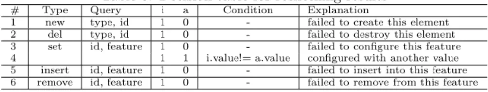
Step 7. Check the synchronization result. The synchronization is over at Step 6, but we have to inform management agents that some of their mod-ifications do not have expected result. We do this by get an intended differ-ence from Original Arch to Modified Arch, and an acutal difference from Original Arch to Final Arch, and then check if the intendedmodifications all remains in the actualmodification. The decision table used for this check is showed in Table 6.
an exception. In our example, we have a pair (set(#MySQL,maxPool,1000), set(#MySL,maxPool,100))satisfying #4 situation, and this will be reported to the managed agent. Note that we do not consider (0,1) situations as exceptions, for example the actual difference contains anew(Component,#HSQL) while the intended one does not a corresponding operation. Although this situation is not the agent’s intention, it does notconflict with the agent’s intention.
5.3
About the properties
In this section, we discuss how this algorithm satisfy the four properties we listed in Section 2.
Property 1. Synchronization leading consistency. According to the “Cor-rectness” property discussed in literature [22], after the backward transforma-tion,Final Arch andFinal Syssatisfy the relation specified in QVT. There-fore, synchronization always result consistent architectural model and system state.
Property 2. Non-interference reading. If the Original Arch and the Modified Archequal to each other, we will get equalOriginal SysandModified Sys, so the difference between them is empty, and thusDesired sysequals to Current Sys. Finally, the empty difference betweenDesired sysandCurrent Syswill not cause any modification to the system adapter.
Property 3. Effective writing. For normal conditions, this algorithm can satisfy this property. The modifications on architecture side will be translated to a proper modification stored in the difference between Desired sys and Current Sys, and this modification will cause reconfiguration in the system through the system adapter, and the correct reconfiguration result will be re-flected. But as we have discussed before, there exists some kinds of exception conditions, e.g. the modification on systems does not lead expected result, or the modified part in architectural model cannot be transformed into the system model. For such situations, we will inform the management agents.
Property 4. No insignificant change. If the modified architectural model and the current system state satisfy the relation, thenDesired Sys will equal toCurrent Sys, and there will be no reconfiguration operations on the system adapter. So the system will not be changed. Furthermore, according to the “Hippocraticness” property [22], when executing the backward transformation, theModified Archwill not be changed.
5.4
Implementation and discussion
Figure 5: Process for constructing an infrastructure under our framework
Note that our algorithm depends on one assumption, i.e. during the syn-chronization process, the system state does not change. This assumption is reasonable if the synchronization can be executed quickly enough, and in our case study, this situation is satisfied. If in the actual usage, the system state change too frequently, management agents have to lock the system state before execute the synchronization.
6
Case Study
In this section, we report our case study for constructing an infrastructure to support runtime management of JOnAS systems based on C2-styled architecture model. We choose JOnAS as a target platform because JOnAS is a widely used open source J2EE application server, achieving the scale of systems in actual use. Moreover, we can use a well know application, JPS, to evaluate the effect of the generated infrastructure, and use the build-in JOnAS admin tool as a reference. We choose C2 styled architectural model in this case study because C2 is a well-researched architecture style and its advantages on managing GUI systems are widely accepted.
We have briefly revealed the effect this constructed infrastructure in Sec-tion 2.1, and in this secSec-tion, we will focus on how we construct this infrastruc-ture based on our framework, demonstrating that our framework can improve this constructing process to be productive.
6.1
Constructing the runtime architecture infrastructure
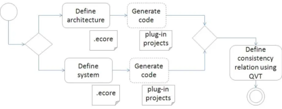
Our framework is implemented as several Eclipse plug-ins, depending on a num-ber of reusable plug-ins or libraries like EMF, medini QVT, Beanbag, etc. The whole constructing process is performed under Eclipse environment, as shown in Figure 5.
Figure 6: Meta-models for architecture and system
Table 7: Manual, generated and framework artifacts
item artifact quantified workload
Man
ual define C2define JOnAS Ecore modelEcore model 2961 model elementsmodel elements add annotation Java code 474 LOC
define relation QVT text 207 LOC
Gen.
for arc Java code 8761 LOC for sys Java code 18263 LOC
F
ra. common meta-model Ecore model 17 model elements
Synch. and utility Java code 2130 LOC* *exclude reused libraries and plug-ins
Second, we construct another Ecore meta-model to specify the kind of sys-tem states as show in the right part of Figure 6. This meta-model contains classes likeEntityBean,WebModule,DataSource, etc. according to the types of MBeans provided by JOnAS JMX with same names. We add some attributes into these classes according to the attributes of corresponding MBean types. The inheritance structure between these classes agrees with the class hierarchy defined between the MBean classes. MBeanServer is a special class defining the JOnAS server itself. We also add annotations to these meta-model ele-ments with the JMX specific code for accessing JOnAS server. An example of these annotations can be found in Table 3. We also use EMF to generate three projects.
Third and last, we define a QVT transformation to specify the consistency relation we expect between architectural models and system states. In Table 5, we list 2 of the 6 relations we defined.
Table 6.1 lists the quantified manual workload for implementing this case, comparing with the size of generated code and framework. From the simple comparison we can at least conclude that that our framework does save some effort for developers. We have not found a manual-developed runtime architec-ture infrastrucarchitec-ture with same capabilities as a control sample, but we believe that seven hundred lines of code is not a heavy load for a developer familiar with JOnAS JMX, and neither is the one hundred of model elements for a developer familiar with EMF and QVT.
6.2
Using the constructed infrastructure
Table 8: Synchronization time spent
No. modifications on arch. model sync. time spend
1 - 5137 ms
2 - 3012 ms
3 change 1 attribute value 2917 ms 4 change 10 attribute value 3105 ms 5 add 1 WebModule 3262 ms 5 remove 1 WebModule and add 2 EJB 3327 ms 6 relink between WebModule and EJB 3329 ms
platform. After launching this Eclipse, we can create a empty project, and copy the two meta-models and the QVT file into this project. Now we can import an architecture model or create an empty one, modify it with text editor or a tree-based model editor provided by eclipse, and synchronize it with a running JOnAS system by clicking a tool-bar button.
In this case study, to intuitively reveal the effect of this infrastructure, we also use Eclipse GMF to generate a graphical editor for the architectural model, as shown in Figure 1. To generate this graphical editor, we created 3 GMF required models with 34 model elements in total, without writing a single line of code. Notice that is work is actually outside the scope of our framework, since it is only in charge of maintaining the causal connection.
We have briefly shown the effect of using this infrastructure in Section 2, through some basic scenarios for runtime management of the JPS application.
We did an experiment on the infrastructure constructed in this case study, on a laptop computer with an Intel Pentium M 1.6GHz process, and 1.5G mem-ory. The Eclipse 3.4 platform, which is the host of architecture editor and our infrastructure, and a JOnAS 4.9.7 application server are all running on this same computer. The architectural model contains 69 components and connec-tors, while the JOnAS server contains over 300 manageable elements (MBeans), and 47 elements among them, along with over 100 attributes will be reflected to the architecture model. The experiment result is listed in Table 8.
The number in the first column represents the order for executing “synchro-nization”. The first synchronization took quite a long time, and we doubt it is because the JVM has to load many classes from the relevant plug-ins and libraries. The 6th synchronization took the second long time because in our current wrapping, to change a EJB reference, we have to reload the EJB or the Web Module.
6.3
Discussion on some other concerns
Performance As an initial attempt, we did not pay too much attention on the performance of constructed infrastructures, although performance is also an important concerns. The experiment above shows that although this infras-tructure’s performance is not good, but it is still acceptable. Several seconds of time spent are reasonable for manual management. We have tried to use the build-in JOnAS Admin web page to deploy a WebModule, and after clicking the “confirm” button, we also have to wait for more than a second until the whole page is refreshed.
automated management agents, like self-adaptation engine. We will emphasize on the performance in our further work.
Maintainability and incremental development We are not very familiar with JOnAS JMX interface, and thus we made some mistakes when filling the hook method. So, the first version of the constructed infrastructure also have some defects, like receiving exception when reading some attribute. Since the specific code are directly mapped to elements, attributes or references, we can easily locate the mistakes from a few lines of code in annotations. We think this is a reflection of the maintainability of infrastructures constructed under our framework. We also tried to reflect extra kinds of manageable elements into ar-chitectural models, and the experiment confirm that we just need tosupplement
the meta-models, QVT transformation, without breaking the existing effort. So we can also say that our framework is good for incremental development.
7
Related Work
There are many approaches toward runtime architectures, focusing on different aspects. Some of them focus on the low-level mechanisms for retrieving and updating runtime states [5], and for ensuring the consistency of the running system after reconfiguration [17, 24]. Some other researchers focus on the high-level representation and specification of the running system for intelligibility and usability [17], for automatically executing or evaluating the reconfiguration [18], or even for self adaptation [11]. There are also approaches toward constraining the runtime change from architecture level, and relevant approaches can be found in the surveys [6].
Distinguished from these typical approaches, we focus on the issue of con-structing infrastructures to automatically maintain the causal connections, and allow developers to choose or construct their preferred architecture style and runtime system. This issue is not emphasized in most of the existing approaches, but it is important for the practical use of runtime architectures. By assisting developers to easily combine runtime systems with architecture models, we actu-ally provide an attempt toward leveraging the sorts of research results mentioned above. We wish our common solution to this necessary issue can also help re-searchers on runtime architectures to continue concentrating on the proper forms or usages of architecture models, or the low-level mechanisms for manipulating runtime systems, without worrying about how to connect them together.
Among the existing approaches on runtime architectures, Rainbow [11] shares the most commonality with ours. The difference is that Rainbow provides a common structure and guidance for constructing different runtime architecture infrastructures, and help reusing knowledge between the constructions, but we provide a generating approach for constructing such infrastructures.
8
Conclusion
In this paper, we report our initial attempt towards a model-driven framework for constructing runtime architecture infrastructures. Under this framework, developers only need to write two MOF meta-models and a QVT transformation between them. The tools we implement will automatically generate code from the two meta-models for accessing architectural models and system states, and a common synchronization engine will maintain the causal connection according to the QVT transformation.
We do not wish to provide complete support for runtime architectures, but only put emphasis on maintaining causal connections. Developers still have to design the proper architecture style for their usage, and instrument their target systems with management capability at runtim. As there are already many research approaches on architecture styles and management capabilities, subsequent researchers can use our approach combining with these existing ones. As an initial attempt towards flexible approach on runtime architecture, we current ignored some technical issues. One of these issues is about fault-tolerance. The mistake in the specification of causal connection or the inaccu-rate wrapping of management capability will all cause unexpected behavior of the infrastructure. We had a discussion about these exceptions in Section 5, but our current solution still remains at the step of “informing something is wrong” In the future, we’ll try to find effective approaches to tolerating the faults in specifications, providing constructive information from the analysis of exceptions, or assisting developers in deriving correct specifications. Currently, we also paid little attention on the performance, which is a key issue for the scalability of the infrastructure.
A model-based extensible infrastructure also has some additional features. First, using MOF to define architecture styles will help reuse management poli-cies between different approaches. Second, by explicitly specifying the causal connections under QVT, it is possible to inspect, analyze, or even verify the runtime architecture infrastructures before they are actually used. We plan to give further research on these concerns.
Acknowledgment
The research was supported in part by the Natural Science Foundation of China under Grant No. 60528006, the National Basic Research Program of China (973) under Grant No. 2005CB321805the High-Tech Research and Development Pro-gram of China under Grant No. 2007AA010301, the Science Fund for Creative Research Groups of China under Grant No. 60821003
References
[1] Marcus Alanen and Ivan Porres. Difference and union of models. In The 6th Unified Modeling Language (UML), volume 2863 of Lecture Notes in Computer Science, pages 2–17. Springer, 2003.
Languages and Systems, 9th International Conference (MoDELS), pages 692–706, 2006.
[3] N. Bencomo, G. Blair, and R. France. Summary of the workshop [email protected] at MoDELS 2006. In Lecture Notes in Computer Science, Satellite Events at the MoDELS 2006 Conference, LNCS,, pages 226–230, 2006.
[4] N. Bencomo, P. Grace, C. Flores, D. Hughes, and G. Blair. Genie: Support-ing the model driven development of reflective, component-based adaptive systems. In International Conference on Software Engineering (ICSE), pages 811–814, 2008.
[5] G.S. Blair, G. Coulson, P. Robin, and M. Papathomas. An architec-ture for next generation middleware. InIFIP International Conference on Distributed Systems Platforms and Open Distributed Processing. Springer-Verlag, 1998.
[6] Jeremy S. Bradbury, James R. Cordy, J¨urgen Dingel, and Michel Wer-melinger. A survey of self-management in dynamic software architecture specifications. InThe 1st ACM SIGSOFT Workshop on Self-Managed Sys-tems (WOSS), pages 28–33, 2004.
[7] F. Budinsky, S.A. Brodsky, and E. Merks. Eclipse Modeling Frame-work. Pearson Education, project address: http://www.eclipse.org/ modeling/emf.
[8] Catalog of OMG Modeling and Metadata Specifications,http://www.omg. org/technology/documents/modeling_spec_catalog.htm.
[9] J. Nathan Foster, Michael B. Greenwald, Jonathan T. Moore, Benjamin C. Pierce, and Alan Schmitt. Combinators for bidirectional tree transforma-tions: A linguistic approach to the view-update problem. ACM Trans. Program. Lang. Syst., 29(3):17, 2007.
[10] Robert France and Bernhard Rumpe. Model-driven development of com-plex software: A research roadmap. In Future of Software Engineering (FOSE) in ICSE ’07, pages 37–54, Washington, DC, USA, 2007. IEEE Computer Society.
[11] David Garlan, Shang-Wen Cheng, An-Cheng Huang, Bradley R. Schmerl, and Peter Steenkiste. Rainbow: Architecture-based self-adaptation with reusable infrastructure. IEEE Computer, 37(10):46–54, 2004.
[12] Holger Giese and Robert Wagner. Incremental model synchronization with triple graph grammars. InModel Driven Engineering Languages and Sys-tems, 9th International Conference (MoDELS), pages 543–557, 2006.
[13] Gang Huang, Hong Mei, and Fuqing Yang. Runtime recovery and manipu-lation of software architecture of component-based systems. Autom. Softw. Eng., 13(2):257–281, 2006.
[15] Java PetStore, http://java.sun.com/developer/releases/petstore/. [16] JOnAS Project. Java Open Application Server, http://jonas.
objectweb.org.
[17] Jeff Kramer and Jeff Magee. The evolving philosophers problem: Dynamic change management. IEEE Trans. Softw. Eng., 16(11):1293–1306, 1990.
[18] Peyman Oreizy, Nenad Medvidovic, and Richard N. Taylor. Architecture-based runtime software evolution. InProceedings of the 20th international conference on Software engineering (ICSE), pages 177–186, Washington, DC, USA, 1998. IEEE Computer Society.
[19] Peyman Oreizy, Nenad Medvidovic, and Richard N. Taylor. Runtime soft-ware adaptation: framework, approaches, and styles. InICSE Companion ’08: Companion of the 30th international conference on Software engineer-ing, pages 899–910, New York, NY, USA, 2008. ACM.
[20] Bradley Schmerl, Jonathan Aldrich, David Garlan, Rick Kazman, and Hong Yan. Discovering architectures from running systems. IEEE Trans. Softw. Eng., 32(7):454–466, 2006.
[21] Sylvain Sicard, Fabienne Boyer, and Noel De Palma. Using components for architecture-based management: the self-repair case. InICSE ’08: Pro-ceedings of the 30th international conference on Software engineering, pages 101–110, New York, NY, USA, 2008. ACM.
[22] Perdita Stevens. Bidirectional model transformations in QVT: Semantic issues and open questions. In Model Driven Engineering Languages and Systems, 10th International Conference, MoDELS 2007, Nashville, USA, September 30 - October 5, 2007, Proceedings, volume 4735 ofLecture Notes in Computer Science, pages 1–15, 2007.
[23] Yingfei Xiong, Zhenjiang Hu, Haiyan Zhao, Masato Takeichi, Hui Song, and Hong Mei. Beanbag: Operation-based synchronization with intra-relations. InGRACE Technical Report GRACE-TR-2008-04, 2008.
Appendix A.
Sample meta-model for defining data sources in JOnAS
P a c k a g e ( name = " J O n A S J M X " ){
Annotation(source= " http :// www . sei . pku . edu . cn / rsa " ){ " m a i n E n t r y " - >{
...
m g m t H o m e = ( M a n a g e m e n t H o m e ) P o r t a b l e R e m o t e O b j e c t . narrow (
i n i t i a l C o n t e x t . lookup ( " ejb / mgmt / MEJB " ) , M a n a g e m e n t H o m e . class );
return m g m t H o m e . create (); }
Class( name = " J D B C D a t a S o u r c e " ){
Annotation(source= " http :// www . sei . pku . edu . cn / rsa " ){ " r a w t y p e " - >{ javax . m a n a g e m e n t . O b j e c t N a m e }
" create " - >{ ...
$ m a i n E n t r y . invoke ( dbServerce , " l o a d D a t a S o u r c e " ,
new String []{ g e t N a m e () , pro , new B o ol e a n ( true )} , new String []{ " java . lang . String " ,
" java . util . P r o p e r t i e s " , " java . lang . B o o l e a n " } )
}
" d e s t r o y " - >{...} }
Attribute( name = " j d b c M a x C o n n P o o l " , type = Interger , u p p e r b o u n d =1) {
Annotation(source= " http :// www . sei . pku . edu . cn / rsa " ){ " get " - >{
if ( $core == null ) return " " ; $ f e a t u r e N a m e = $ m a i n E n t r y
. g e t A t t r i b u t e ( $core , $ f e a t u r e ); }
" set " - >{...} }
} ... }
Class( name = " M B e a n S e r v e r " ){
A s s o c i a t i o n ( name = " j d b c D a t a S o u r c e " , c o n t a i n m e n t = true ){
Annotation(source= " http :// www . sei . pku . edu . cn / rsa " ){ list - >{
O b j e c t N a m e query = new O b j e c t N a m e ( " jonas : j 2 e e T y p e = $ f e a t u r N a m e " ); Set sets = $ m a i n E n t r y . q u e r y N a m e s ( query , null );
$ r e t u r n . addAll ( sets ); }
add - >{...} ...
}
Code generated from the above meta-model
public c l a s s J O n A S P a c k a g e I m p l extends E P a c k a g e I m p l ...{ ...
public M a n a g e m e n t g e t M a i n E n t r y (){ ...
} }
public c l a s s M B e a n S e r v e r I m p l extends W r a p p i n g E O b j e c t I m p l ...{
public List l i s t S u b C o r e s (int f e a t u r e I D ){
switch( f e a t u r e I D ){
case J O n A S P a c k a g e . M B E A N _ S E R V E R _ _ J D B C _ D A T A _ S O U R C E :
...
pack . g e t M a i n E n t r y . invoke ( dbServerce , " l o a d D a t a S o u r c e " ,
new String []{ " java . lang . String " , " java . util . P r o p e r t i e s " , " java . lang . B o o l e a n " } )
break; ... }
public EList < J D B C D a t a S o u r c e > g e t J d b c D a t a S o u r c e () {
i f ( j d b c D a t a S o u r c e == null) {
j d b c D a t a S o u r c e = new
E O b j e c t C o n t a i n m e n t E L i s t F o r W r a p p i n g < J D B C D a t a S o u r c e >(
J D B C D a t a S o u r c e .class,
this,
J O n A S P a c k a g e . M B E A N _ S E R V E R _ _ J D B C _ D A T A _ S O U R C E , J O n A S P a c k a g e . e I N S T A N C E . g e t J D B C D a t a S o u r c e () );
}
(( E O b j e c t C o n t a i n m e n t E L i s t F o r W r a p p i n g < J D B C D a t a S o u rc e >) j d b c D a t a S o u r c e ). r e f r e s h W r a p ();
return j d b c D a t a S o u r c e ; }
public Object eGet (int featureID ,boolean resolve ,boolean c o r e T y p e ){
switch ( f e a t u r e I D ) {
case J O n A S P a c k a g e . M B E A N _ S E R V E R _ _ J D B C _ D A T A _ S O U R C E :
return g e t J d b c D a t a S o u r c e (); ...
} ... }
public c l a s s J D B C D a t a S o u r c e I m p l ...{
The complete QVT specifying relation between C2 and JOnAS
transformation C 2 J O n A S ( arc : C2 , sys : JOnAS ){ key C2 :: C o n n e c t o r { name };
key C2 :: C o m p o n e n t { name };
key C2 :: A r c h i t e c t u r e { d e p l o y e d H o s t }; key JOnAS :: M B e a n S e r v e r { s e r v e r H o s t }; key JOnAS :: EJB { name };
key JOnAS :: W e b M o d u l e { name };
top relation R o o t 2 R o o t {
host : String;
enforce domain arc s : C2 :: A r c h i t e c t u r e { d e p l o y e d H o s t = host
};
enforce domain sys t : JOnAS :: M B e a n S e r v e r { s e r v e r H o s t = host
};
when {
s . parent . o c l I s U n d e f i n e d (); }
}
top relation C o m p o n e n t 2 E n t i t y B e a n {
name : String;
a d d r e s s : String;
f i l e P a t h : String;
jdbc :String;
checkonly domain arc arch : C2 :: A r c h i t e c t u r e {};
enforce domain arc conn : C2 :: C o n n e c t o r { name = a d d r e s s
};
enforce domain arc comp : C2 :: C o m p o n e n t { name = name ,
a d d r e s s = address , f i l e P a t h = filePath , type = ’ Entity ’ , below = conn ,
name = jdbc }
};
checkonly domain sys m b e a n s e r v e r : JOnAS :: M B e a n S e r v e r { };
enforce domain sys e n t i t y b e a n : JOnAS :: E n t i t y B e a n { name = name ,
j n d i N a m e = address , f i l e N a m e = filePath , parent = mbeanserver , d a t a S o u r c e J N D I = jdbc };
when {
R o o t 2 R o o t ( arch , m b e a n s e r v e r ); }
}
top relation C o m p o n e n t 2 S t a t e f u l S e s s i o n B e a n {
name : String;
a d d r e s s : String;
f i l e P a t h : String;
i n s t a n c e L i f e : Integer;
checkonly domain arc arch : C2 :: A r c h i t e c t u r e {};
enforce domain arc conn : C2 :: C o n n e c t o r { name = a d d r e s s
};
enforce domain arc comp : C2 :: C o m p o n e n t { name = name ,
a d d r e s s = address , f i l e P a t h = filePath , type = ’ D u r a t i v e O p e r a t i o n ’ , below = conn ,
i n s t a n c e L i f e = i n s t a n c e L i f e };
checkonly domain sys server : JOnAS :: M B e a n S e r v e r { };
enforce domain sys sb : JOnAS :: S t a t e f u l S e s s i o n B e a n { name = name ,
j n d i N a m e = address , f i l e N a m e = filePath , parent = server ,
s e s s i o n T i m e O u t = i n s t a n c e L i f e };
when {
R o o t 2 R o o t ( arch , server ); }
}
top relation C o m p o n e n t 2 S t a t e l e s s S e s s i o n B e a n {
name : String;
a d d r e s s : String;
f i l e P a t h : String;
i n s t a n c e L i f e : Integer;
jdbc : String;
checkonly domain arc arch : C2 :: A r c h i t e c t u r e {};
enforce domain arc conn : C2 :: C o n n e c t o r { name = a d d r e s s
};
enforce domain arc comp : C2 :: C o m p o n e n t { name = name ,
a d d r e s s = address , f i l e P a t h = filePath , type = ’ O n e S t o p O p e r a t i o n ’ , i n s t a n c e L i f e = instanceLife , below = conn ,
above = conn2 : C2 :: C o n n e c t o r { name = jdbc
} };
checkonly domain sys server : JOnAS :: M B e a n S e r v e r { };